
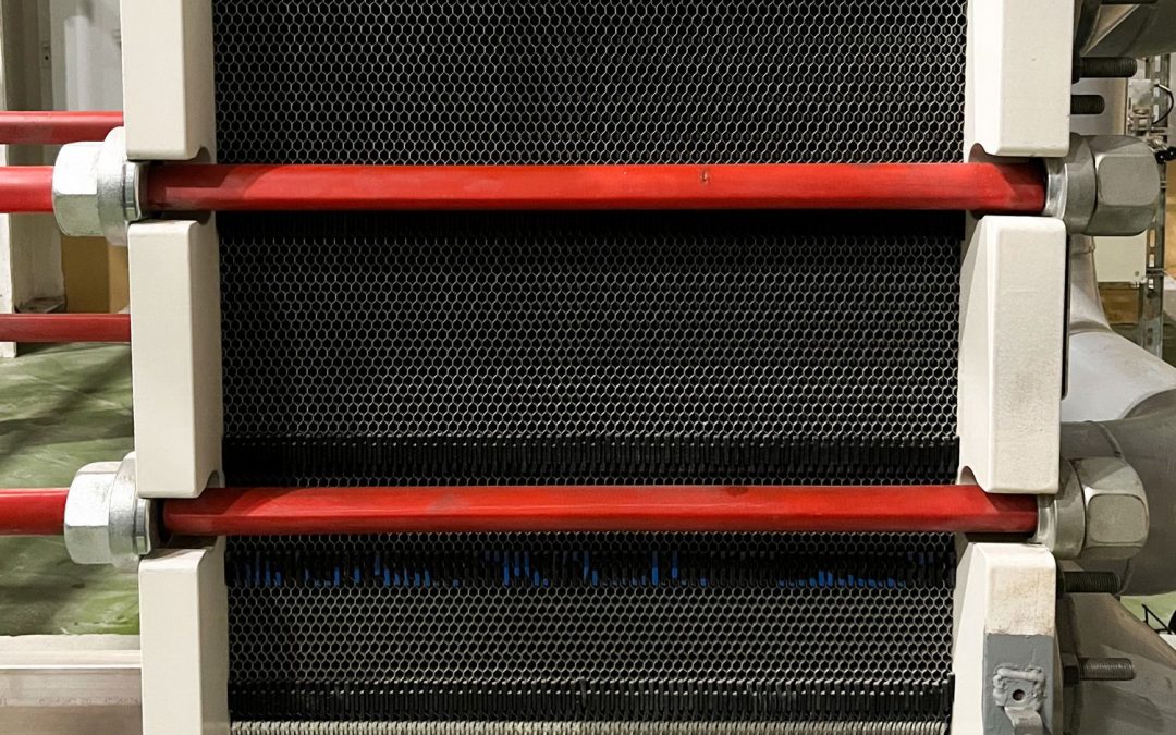
Plate-fin heat exchangers (PFHEs) are at the heart of most cryogenic processes, including LNG plants, air separation units (ASUs), and hydrogen liquefaction systems. Their compact design, high heat transfer efficiency, and ability to handle multiple process streams make them the preferred choice for cryogenic heat exchange. However, their performance depends heavily on fin geometry, flow distribution, and operating conditions.
Fin Geometry Drives Performance
The fin design has a major influence on both heat transfer and pressure drop. Engineers must find the right balance for each individual process stream.
Plain fins create a relatively low pressure drop but provide lower heat transfer performance. They are often selected when minimizing pressure losses is the main priority.
Serrated or offset strip fins are the most common choice in cryogenic applications. They disrupt the boundary layer, significantly improving heat transfer while maintaining a reasonable pressure drop.
Perforated fins promote additional mixing within the channels and offer a good compromise between thermal performance and hydraulic losses.
Wavy or louvered fins generate the highest heat transfer rates by continuously redirecting the flow. However, they also create higher pressure drops and increase manufacturing complexity.
Rather than selecting one fin type for the entire exchanger, designers usually optimize each stream independently according to its temperature, pressure, flow rate, and fluid properties.
High Effectiveness with Small Temperature Differences
One of the main advantages of a PFHE is its ability to recover heat with extremely small temperature differences. Approach temperatures of only 1 to 3°C are common in cryogenic applications.
This high effectiveness comes from the exchanger’s exceptional surface area density, which can exceed 1,000 m² per cubic metre, combined with efficient fin designs and true multi-stream capability.
Reducing the temperature approach improves process efficiency but also increases the size and cost of the exchanger. As performance targets become more demanding, maintaining uniform flow distribution becomes increasingly important.
Flow Distribution Is Critical
A PFHE only reaches its design performance when every channel receives the correct flow. Even small maldistribution can reduce heat exchanger efficiency.
Poor header design, manufacturing tolerances, or two-phase flow can cause some channels to carry more flow than others. The result is reduced thermal performance, local temperature pinch violations, and, in severe cases, freezing or hot spots within the core.
For this reason, flow distribution is often just as important as the thermal design itself.
Brazed Aluminium Construction
Most PFHEs use vacuum-brazed aluminium cores. Aluminium provides excellent thermal conductivity while keeping the exchanger lightweight and compact. The brazed construction also eliminates the need for gaskets and allows several process streams to operate within a single core.
Despite these advantages, brazed aluminium heat exchangers have operating limits. They are generally suitable for temperatures between approximately -270°C and +65°C and are sensitive to repeated thermal cycling.
Pressure limits are also relatively low compared with other heat exchanger technologies, and designers must carefully control differential pressure between adjacent streams.
Cleanliness is equally critical. Oil, moisture, or solid particles can permanently foul the narrow flow passages, and repairing a damaged PFHE is often impossible, making replacement the only practical solution.
Design Considerations
Designing a high-performance PFHE requires more than thermal calculations. Engineers must optimize fin geometry, header design, pressure drop, and flow distribution while keeping the exchanger within its mechanical limits.
Maintaining clean process streams is equally important, as contamination remains one of the most common causes of long-term performance degradation.
Conclusion
Plate-fin heat exchangers offer unmatched efficiency and compactness for cryogenic applications. Their ability to exchange heat between multiple streams with very small temperature differences makes them indispensable in modern LNG, hydrogen, and industrial gas plants.
Achieving this performance, however, requires careful attention to fin selection, flow distribution, operating conditions, and gas cleanliness. In cryogenic engineering, the best PFHE design combines excellent thermal performance with robust operation over the entire life of the plant.

References and further reading
- Cryogenics (Elsevier) — peer-reviewed journal on cryogenic engineering
- NASA Technical Reports Server (NTRS) — cryogenic research papers
- Linde Engineering — air separation and liquefaction technology
- Chart Industries — cryogenic equipment and storage systems
- International Institute of Refrigeration (IIR)
Continue reading on The Cryoexpert
- Cryogenic Distillation Columns
- Cold Box Design Principles
- Heat Transfer at Cryogenic Temperatures
- Cryogenic Compressors
- Cryogenic Vaporization Technologies
Working on a cryogenic project?
Get expert engineering support for ASU, cryogenic storage, vacuum insulated piping, vaporization and regasification projects — from feasibility studies to commissioning. Tell us about your project and get a response within one business day.